BreadBot 16 -- an autonomous, six-wheeled rover based on the Raspberry Pi
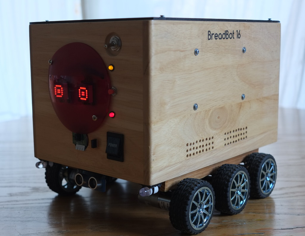
BreadBot-16 is a small, autonomous six-wheeled rover based on the Raspberry Pi. It uses ultrasonic sensors for collision avoidance and can explore without human control. Alternatively it can be controlled from a Web interface, using a picture feed from a camera module. It has an amplifier and speaker for audible (spoken) feedback. The whole thing is built in a small breadbox, for no better reason than that I happened to have one, and it was about the right size. Animated "eyes" at the front give visual cues to the decision-making process when the unit is operating autonomously.
The motors are low-geared so the top speed is modest; but their high torque allows Breadbot to negotiate slopes and uneven ground.
BreadBot-16 is programmed entirely in C, using a collection of independent modules that communicate using the Mosquitto message bus.
This article describes the design and construction of the project -- in particular the challenges it presented, and what I could have done better, had I known then, what I know now. This article is intended for people who are contemplating their own Raspberry Pi robotics projects, and would like to know what to expect. Building Breadbot requires some knowledge of electronics, and elementary workshop skills, including woodwork. However, companies like PiBorg -- from whom I purchased the motors and some of the electronic components -- can supply complete self-assembly kits, with programming examples in Python.
Chassis
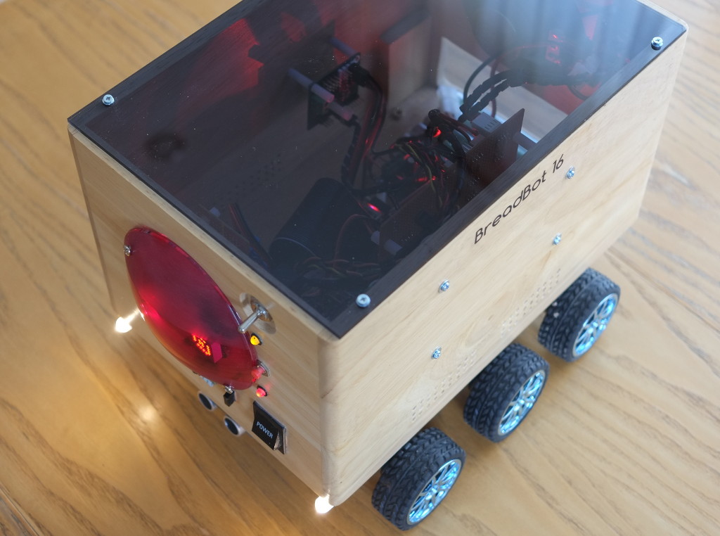
BreadBot-16 is built around a small wooden breadbox -- the plan elevation of the box is almost exactly the same as an A4 sheet of paper.
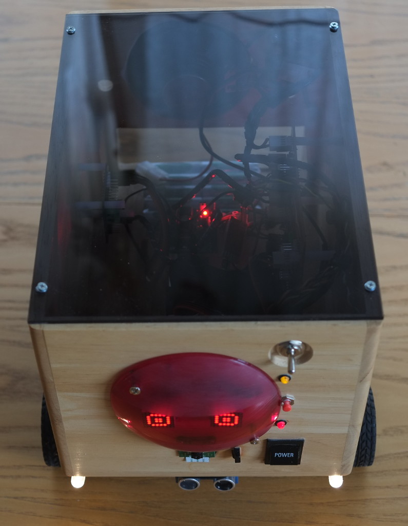
The smoked acrylic lid allows the internal workings to be seen -- whether that's a good thing is a matter of taste, of course. However, it reduces the weight considerably, compared to the original, inch-thick wooden lid. The other LEDs on the front show the status of the 12V and 5V power supplies. The red dome is a photographer's lighting gel, which just happens to be a perfect match for the colour of the light from the LED "eyes", masking the electronics and wiring of the Adafruit LED modules. Below the dome are the camera module and infrared light sensor.
Weight is a consideration here -- wood is not an ideal building material for a project of this sort, but it's inexpensive and easy to work.
Raspberry Pi
The core of the project is a Raspberry Pi, running the Minibian Linux distribution.
Minibian is a minimal Linux that contains no graphical or desktop software. This distribution only takes about seven seconds to boot on the Pi, and this can be pared down even further by removing the few inessential services. In addition, it's relatively easy to convert to a read-only-root filesystem, which is useful if you want to be able to switch off safely just by throwing a switch.
If I were starting again, I'd create my own custom Linux installation for the Pi, but I didn't know how to do that when I started this project.
The Pi uses a micro-SD card for storage. The micro-SD slots on some of these units are not of high quality, and the card needs to be fastened in place (tie-wrap, duct tape...) to prevent it springing out when Breadbot goes over a bump. I admit, though, that I've used Raspberry Pi boards more recently and not had any problems of this sort.
Motors
I purchased the motors complete with wheels, tyres and mounting brackets. This isn't very cost-effective, but at least everything will fit together. The motors have built-in gearboxes to give a final shaft speed of 60rpm. Naturally there's a trade-off between speed and torque, but high torque is more important in this application, as the finished unit is quite heavy (about 3Kg).
The motors draw about 200mA each at their rated 6V when running on level, smooth ground -- that's a power of about 7W.
The motors are mounted on wooden rails, to allow the tyres to clear the bottom of the breadbox. These rails contribute significantly to the weight, but they do allow the motors to be adjusted as sets of three, rather than individually. Getting the motor spindles perfectly parallel is critical to even and straight running; this was the most fiddly part of the mechanical construction.
With the motor positions carefully adjusted, Breadbot does run in a near-perfect straight line when the left and right controllers are set to the same power output. If that isn't the case -- and it might just be a happy coincidence -- then I imagine some adjustment could be made in software.
Motor control
BreadBot-16's motors are controlled by a PiBorg Reverse. It's a two-channel PWM controller, which means that the motor current is either fully on or fully off, and the motor speed is regulated by adjusting the balance of "on" and "off" time (the duty cycle). The PWM frequency is above the audible range (unless you're a dog) so the motors don't whine, whatever the power setting.
The Reverse connects to the I2C bus and, in principle, has a 5A per channel current capacity. As with all PWM controllers, the heat dissipation in the controller does not depend on duty cycle (motor speed), only on the supply voltage and the characteristics of the motor. This means that if you use motors that draw 5A, you'll need a controller rated at 5A (or more) even if you plan to run them at only a fraction of their rated power. I would guess that some kind of heatsinking would be beneficial in such a set-up. In practice, the motors I'm using only seem to draw about 1A between them, and the Reverse switches do not seem to get noticeably warm.
It's worth bearing in mind that, although the motors will draw 1A (or so) during the "on" part of the PWM duty cycle, the average current supplied to the motors will depend on the motor speed as, of course, will the charge drawn from the batteries.
The Reverse has a handy LED on board which is switched using the same sort of I2C commands as the motors. This makes it easy to test that your control software is doing broadly the right thing, even before you attach the motors.
PiBorg provides software examples for controlling the Reverse in (sigh) Python. Doing it in C is not a problem, however: it's just a matter of sending the appropriate I2C command byte and data value. Here is an example that turns on the on-board LED:
int f = open ("/dev/i2c-1", O_RDWR);
ioctl(f, I2C_SLAVE, 0x44); // Select the Reverse on the bus
unit8_t buff[1];
buff[0] = 1;  // Code to set LED
buff[1] = 1;  // 1 = on
write (f, buff, 2);
close (f);
The commands to control the motors are all single-byte values; I'm not going to list them here but by all means contact me if you need more information.
There are a few practical points to watch out for.
- The Reverse board (and, presumably, any similar controller) needs a separate power supply for the motors and the control logic. The Reverse needs 5V for logic, and at least 6V for the motors. Even if your motors could run at 5V you really, don't want to use the same supply for the logic and the motors. First, whatever you're using to generate a 5V supply is going to have to supply the full current requirements of the motors, and it probably won't be able to. Second, you're going to put a heap of switching noise on the 5V supply, which might well interfere with the digital electronics. The motor supply needs to be taken direct from the battery, perhaps via a fuse.
- It would seem prudent to use nice thick cables to connect the Reverse to the battery, and the motors to the Reverse. A cable resistance of one ohm doesn't sound a lot, but at 1A current draw that's one watt of energy lost as heat in the wiring, which will reduce your battery life by about 20%.
- The Reverse is nicely designed by PiBorg such that its connections can be daisy-chained to other boards they make. A single cable header carries 5V, 3.3V, ground, and the I2C control and clock lines from board to board. While it's a nice idea, I'm far from sure that powering a bunch of boards (including the Raspberry Pi) this way is optimal in an electrically noisy environment. I've had problems with other Raspberry Pi projects resulting from the supply cables being too resistive. Moreover, it's hard to disconnect a board for troubleshooting if all the electronics is chained together. In the BreadBot, all the supply cables (12V and 5V) and also the I2C wiring, originates from the same custom-made distribution board, and uses reasonably heavy hook-up wire.
- The Reverse is supplied at 12V, but the motor rated voltage is 6V. Keeping the PWM duty cycle at no more than 50%, to avoid damaging the motor, has to be taken care of in software.
Headlights
Breadbot-16's headlights are a couple of nominal 1-watt LED modules. In practice, you need to take these manufacturer's ratings with a pinch of salt -- they are often overestimated. The ones I bought actually consumed about 0.25W each. Still, they're quite bright -- I was going to use four, but two turned out to be sufficient for the camera to see a few metres in the dark. You do have to be a bit careful to adjust them to line up with the camera's axis of vision, but it doesn't have to be perfect.
The LEDs, of course, draw too much current to connect directly to a Raspberry Pi GPIO pin. You can buy custom control modules for this sort of thing but, if you're reasonably handy with a soldering iron, a MOSFET will do the trick a lot more cheaply.
Here's the driver circuit for the headlamps. => img/breadbot-16-7.png Headlamp driver circuit
The MOSFET is hugely over-rated for this application, with a maximum drain current of 30A; but that means no worry about heatsinking or ventilation with the much lower current in use. Note that the LEDs don't need dropper resistors, since they are designed for direct 12V connection.
The G4 LED modules are bright enough, but don't live up to the 1-watt claim made by the vendor
Audio amplifier and speaker
It's quite entertaining to make Breadbot emit R2D2 noises as he trundles about, but spoken feedback makes it a whole lot easier to figure out what's going on, particularly as Breadbot has no graphical display. The Pi's audio output isn't sufficient to operate a speaker, even a small one, so some sort of amplifier is required. There's no need, I guess, for stereo in this application. I used a mono 1-watt amp module from Maplin (now sadly out of business); Adafruit makes one specifically for the Pi, but it's a bit more expensive. Naturally, it needs to be compatible with the battery voltage -- 12V in this case.
The speaker I used was a five-inch unit which, with hindsight, is much to large and heavy for the application. Still, it does mean that Breadbot can double as a desktop media player -- with the wooden case it actually doesn't sound too bad. Still, a two-inch driver would have been enough, and saved about 300g in weight.
For speech synthesis I'm using espeak.
It sounds, well, robotic, but it's very light on system resources, and is available from the standard Raspberry Pi repositories. Festival sounds a whole lot better, but it's CPU-intensive and needs about 80M of storage.
Proximity sensors
The proximity sensors are the common HC-SR04, driven by a PiBorg Ultraborg board. The Ultraborg can accomodate four sensors, although I'm only using two at present -- one front and one rear. It can also control four servo-motors although, again, none are currently in use.
The Ultraborg connects to the Pi's I2C bus. Unlike the Reverse motor controller, which is essentially a write-only device, the Ultraborg's ultrasonic support depends on I2C read operations, which can be a little problematic (see discussion below).
The Ultraborg firmware can do some smoothing of successive distances determined by the sensors but, in practice, some more averaging in software seems to be beneficial. Even smoothed, successive values can vary by +/- 10cm or so even when looking at a stationary object. The ultrasonic sensors are perfectly fine for detecting an imminent collision, but I don't think they would be all that good for, for example, trying to build up a representation of the surroundings by triangulation -- the sensors just aren't that accurate. Still, I confess that I haven't tried yet, so perhaps it will turn out that I'm just being pessimistic [edited to add -- I wasn't. These sensors simply aren't that accurate in a typical domestic environment].
I find that, given the modest speed at which Breadbot travels, taking a distance reading every 100msec is more than sufficient. The transmitter does draw a measurable battery current, and perhaps the interval could be increased even further with no ill effects, or adjusted according to demand.
Camera
BreatBot-16 uses a standard Pi camera module, which connects to a proprietary connector on the Pi using a ribbon cable. An alternative would have been to use an inexpensive USB webcam, which probably would have had the advantage of a built-in microphone. I chose the Pi camera because of reports of its superior picture quality; I am not at all sure that these reports were accurate, in practice. It's raw resolution is pretty good for an inexpensive part, but the images are very noisy in low light, and long exposures are required -- not ideal on a moving platform.
The biggest problem with the Pi camera, however, is its lack of developer support. It's advertised as supporting the standard video-for-Linux (V4L) interface but, if it does, I'm sure I can't find out how. There are no "official" C libraries available for developers to use, and trying to work out how to use the drivers directly by reverse-engineering the "raspistill" utility is unrewarding.
At present the camera is only used for streaming images to a Web browser for remote control, so "raspistill" in time-lapse mode is adequate for the job -- it just writes a succession of still images to the same file, and the webserver picks that file up on behalf of the browser. In future, for image analysis, I may need to use a different camera that supports a documented interface. There is a Python library that supports the Pi camera and it works fine but, you know, it's (sigh) Python.
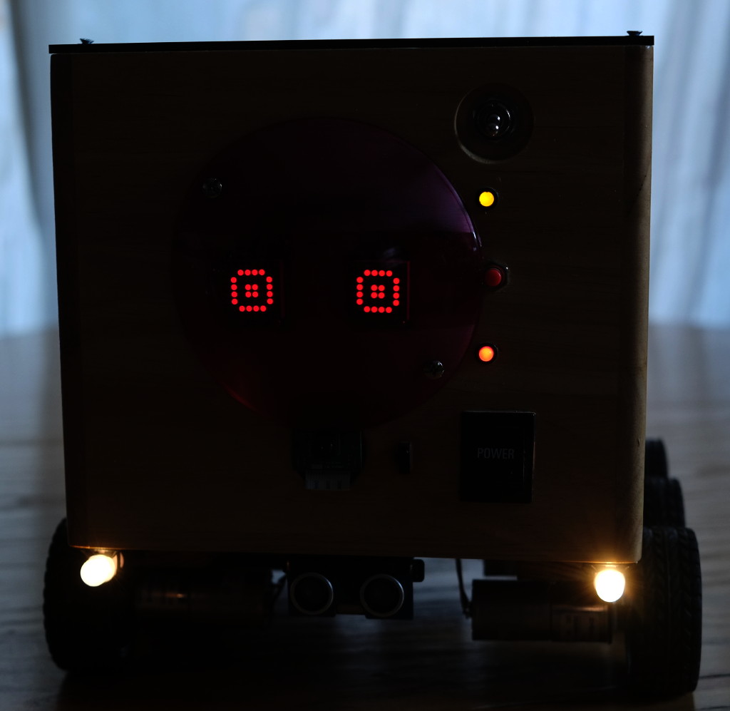
"Eyes"
The animated eyes are partly cosmetic, but they do serve a useful function in providing feedback about Breadbot's decision-making processes. Each eye is an 8-by-8 LED matrix from Adafruit, controlled by the popular HT16K33 I2C-based driver. These modules can be had from eBay for under ten pounds, but you have to solder them up yourself (ten minutes if you know what you're about.) The LEDs are brightness-adjustable using I2C commands and, on minimum brightness, only take a milliamp or so each. However, with a total of 128 LEDs that's still over 100 mA, so the software shuts them down when Breadbot is idle (that is, when the motors aren't driving).
Power supply
BreadBot-16 runs from a pack of 10, 2700 mA-hour NiMH batteries. These can be purchased along with a charger from model or toy shops -- these batteries are often used in model cars and boats. Ten cells in series gives a nomimal 12V. Battery life is not marvellous when the motors are running -- probably less than an hour (see discussion below). There's space in the breadbox to fit a motorcycle-type sealed lead-acid battery; these are available in much higher capacities but, of course, at the expense of increased weight. The motors are capable or pulling the extra weight but, of course, battery life will be reduced. Experimentation will be required to find the best balance of battery size to running time.
The battery directly supplies the motors (via the Reverse board), the audio amplifier, and the headlamps. 5V supplies are needed for the Reverse, Ultraborg, and the Pi itself. The LED "eyes" require a 3.3V supply. The 5V supply is derived from the battery's 12V using a switching DC-to-DC converter; the 3.3V is generated by the Pi itself. I presume that the Pi can supply enough current to operate the LED matrixes (total of 128 LEDs) safely; So far, at least, it seems to be OK.
Assembly and physical layout
There's plenty of room in the chassis for all the parts, but I had to be careful to avoid making cable runs too long, or creating anything that will tend to act as an antenna.
The Raspberry Pi itself is mounted on as near to the centre of the base as it could be; however, it's somewhat nearer to the front because the camera cable is only about eight inches long. It is possible to purchase longer camera cables, but I'm unsure how well they work, particularly in an environment where there's a lot of high-current switching going on.
BreadBot-16 has a custom power-and-signal distribution board mounted within reach of a short ribbon cable from the Pi's GPIO header. All the 12V and 5V supplies are connected to Molex headers on this board, as are all the I2C control lines. It contains the driver for the headlamps, and a connections for the front-panel switches and lamps.
The battery pack is mounted at the rear of the base, held in place with Velcro strips. Nothing much is mounted above the battery pack, leaving the option open to use a much larger battery in future if it proves necessary.
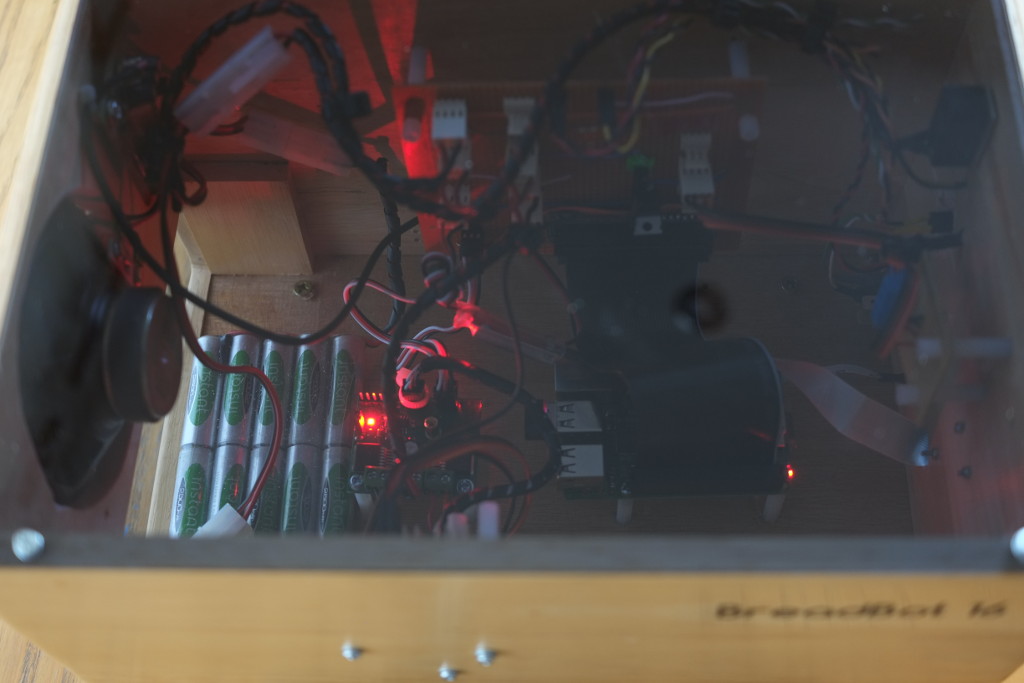
Note that the Raspberry Pi is hidden underneath its own GPIO ribbon cable, which is something that I could have organized better. Overall, there is a compromise between cable organization and cable length: point-to-point wiring between some of the components is unsightly and makes access difficult; but tidier assembly would have made some of the cable runs just far too long to be sure of reliable operation.
Software
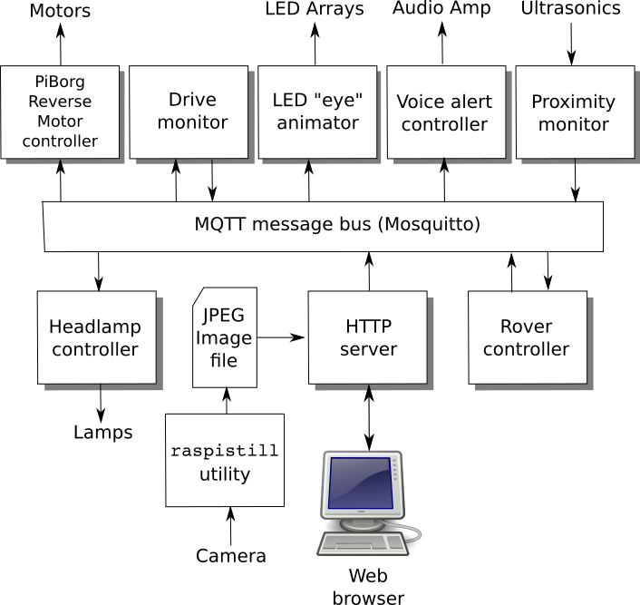
The BreadBot-16 software is designed around a set of software modules of varying complexity, that communicate asynchronously using an MQTT message bus. MQTT is a lightweight messaging protocol designed for telemetry applications. The message bus is dividing into functional topics, and modules subscribe to one or more of these topics to receive notifications from other modules.
I organized the software this way in the hope that it will be more adaptable -- the modules are loosely coupled and can easily be swapped in and out. They are of varying complexity: the 'Headlamp controller' module just listens for notifications and switches a GPIO pin accordingly. The 'Rover controller' module, on the other hand, integrates messages from the proximity sensors, and uses a fairly extensive finite state machine algorithm to make steering choices. The HTTP server provides the manual control interface, as well as feeding images back to the user.
This software is by no means complete, but forms the basis for future experimentation.
Problems and challenges
Here are some of the problems that building Breadbot exposed, not all of which are properly resolved at present.
I2C timing
The Pi I2C driver is a little erratic. It should be possible to put an I2C command on the bus, and then read the response values at leisure. In practice, however, the timing between writes and reads seems to be a bit fussy -- it's necessary to insert pauses between writing an I2C command and reading the result. There doesn't seem to be any way to work out optimal values for these pauses, other than trial and error.
Sending I2C commands that return data to different devices on the bus seems to work OK, so long as there is not too short a gap between reading one device and reading another. Again, in practice, inserting arbitrary delays seems to be necessary. Because Linux is a multi-processing system, the need for delays -- or lack of it -- is hard to determine because timing is complicated by process context switching.
With hindsight, I could have offloaded a lot of the I2C stuff to an Arduino or similar. In fact, I could have done most of the control in an Arduino.
Obstacle detection
The ultrasonic proximity modules really aren't accurate enough to map out a distance profile by rotating the sensors (which means, in practice, the whole chassis). Even if they were, aligning Breadbot in a particular direction is not hugely reliable, particularly on uneven ground. Probably a magnetometer would help here, by allowing the unit to know in exactly which compass direction it is facing when measuring obstacle distance, and distance readings could be averaged to improve accuracy.
At present, however, the unit just has front and rear proximity alerts, which trip at 50cm. The ultrasonic beam width is 22.5 degrees, according to the manufacturer's data sheet, which means that a single sensor can't deal with obstacles that are very far from the axis of the sensor. Moreover, if approaching an obstacle at an angle of more than about 30 degrees, the obstacle isn't seen at all -- the sound beam reflects from the obstacle at the same angle as the angle of incidence, so no reflected sound reaches the receiver. This leads to situations where Breadbot can bump into an obstacle at an oblique angle and not realize he, um... it, has done so.
The simple solution to this problem might be to use extra sensors, oriented at slightly different angles. This is what "Roomba"-like roaming vacuum cleaners have. The Ultraborg can accommodate four sensors. Mechanical bump sensors could also be fitted, as a form of last-resort protection. However, proper obstacle avoidance -- that is part of a program to reach specific locations -- will need more accurate distance profiling, somehow. This is a project for the future.
Steering and drive problems
At present Breadbot steers entirely by "tank steering," that is, it stops, sets the left and right wheels sets to turn in opposing directions for a certain time, and then carries on. Such a manoeuvre can be carried out in very little space. More subtle course changes can be effected by varying the power applied to the left and right motors without actually reversing them, but this isn't very effective in a relative confined space.
The problem with "tank steering" is that the wheel axes of rotation do not lie on a circle -- the manoeuvre will always require some of the tyres to be "dragged" along the axes of their spindles, rather than merely rotating. The tyres are rubber -- they have to be for good grip when moving forward and backward -- and don't slip much on some surfaces.
The problem can be reduced by setting the left and right wheel sets widely separated, compared to the length spanned by the three wheels on each side. So setting adjacent wheels as close together as possible helps with steering, but makes the chassis itself unstable, as it overhangs the wheels at front and rear.
There's no perfect solution to this problem with six motors -- not for indoor use, anyway. On perfectly level ground it would probably be preferable to use two, higher power motors only, with "shopping trolley" balance wheels to support the chassis. Such an arrangement would "tank steer" very effectively, but a two-wheeled design won't handle uneven ground very well.
In practice, "tank" steering is possible on most surfaces if the motors are run at full power. On soft ground, outdoors, all these problems go away. The powerful motors and grippy tires allow Breatbot to run very smoothly in such an environment.
Battery life
Apart from the obvious -- the motors -- the major drain on the battery is the wireless network adapter. When running autonomously the unit does not need a network connection, at least in principle, but it's hard to monitor without one. Interestingly, when the battery starts to run down, the first sign is erratic wireless network operation.
The ultrasonic proximity detectors and the LED "eyes" are also significant energy consumers, as is the camera.
The use of 2700 mA-hr batteries, with a total current consumption of about 1.5A with all motors running, suggests a battery life or nearly two hours. In practice, it's nowhere near that good. With everything running, battery life is 30-40 minutes. The explanation, I think, is that there's still plenty of charge left in the batteries when operation becomes erratic, but not enough to keep the 5V supply to the Pi stable with the motors running. Once the battery capacity runs down to the extent that the motors can no longer run reliably, there's still enough charge to run the Pi board alone for another few hours -- for what good that is.
Running the motors at less than full power would extend the battery life, but not in a practical way -- it would just take longer for Breadbot to get anywhere. There probably are modest energy savings to be made by, for example, optimising the level of activity of the ultrasonic modules, and tuning the wireless network power levels. Even greater savings could be had by making a significant weight reduction, but the largest contributors by far to the overall weight are the motors, and the unit is no good without one. For an indoor-only unit, two motors would be sufficient; outdoors, the extra motors really do make a difference.
In the end, there may be no solution to the problem of restricted battery life, other than to use a much higher-capacity battery. Li-Po batteries offer a higher capacity than NiMH for a particular weight, but they are expensive and fiddly to charge. Sealed lead-acid batteries are available in vast capacities, with a correspondingly vast mass -- the trick with batteries of this sort is to find the best compromise between weight and capacity.
Summary
BreadBot-16 seems to be a reasonably capable platform for experimenting with autonomous, distance-sensing robotic vehicles. Battery life is a little disappointing, and the vehicle does not run all that smoothly on all indoor surfaces, but it's basically functional. Future work will focus on improving the obstacle avoidance, perhaps by fitting an ultrasonic transducer on a rotating servo assembly instead of the present fixed sensors. In due course, I'd like to provide the unit with proper "intelligence", so it can recognize objects in the environment, and respond accordingly.
Published 2021-03-20, updated 2021-03-20
Categories
electronicsConverted from my Gemini capsule.
Please note: This content is moving to a new Gemini capsule, and there's a new HTML mirror here. I won't be updating these pages in future.