Controlling devices by Voltage injection
I have a friend in Ghent, akshay. He got me back onto electronics, which I got him onto in the first place. Strange times. So I bought an ESP32 (C6 variant, this is necessary).
I have a projector at home. Its a shitty chinese projector that can be controlled either by the buttons on it or the remote. How to control the projector with my phone? I can communicate with an esp either via Bluetooth or wifi, but then how to use the ESP32 to control the projector? We have two ways: either emulate the IR Remote or the buttons.
Emulating the IR Remote
This is actually pretty easy. Connect an IR Sensor and an IR Emitter to your ESP. Use IRRemote.h and the arduino programming language (? Environment? I don’t exactly know what it really is actually), to write to serial what was last recorded by the IR Sensor. Most cheap remotes use the NEC protocol, and so did my remote. The buttons are mapped to address 0x0001 and command 0x00 - 0x0C for the 14 buttons on the remote.
This actually works great with the Arduino Uno, but not so much with the esp, for unknown reasons. I also controlled cheap led strips with the same code, which at least worked, but had really poor range. I even tried to drive the led with a 5V source and a transistor, and while it makes it much better, the range is still bad for the strips. The projector however refused to react at all. Why? I don’t know.
Emulating button presses
I could try troubleshooting this, but I felt it would be more fun to emulate the button presses instead. Obviously mechanically doing this is trivial if you had so many motors, but that’s not what I had in mind. There had to be a way to directly signal the projector MC to control it. So I carefully opened up the projector housing, which was unsurprisingly easy.
First Observations
I had predicted that the wiring would be very simple. There would be a wire for each button, and the button would either pull down to ground (typically) or to Vcc (rarely). My ESP would just have to match it, which would be easy if it were < 3.3V as I could directly drive it from the GPIOs, and if not would require a transistor to isolate the voltages.
This is what I saw when I opened it up.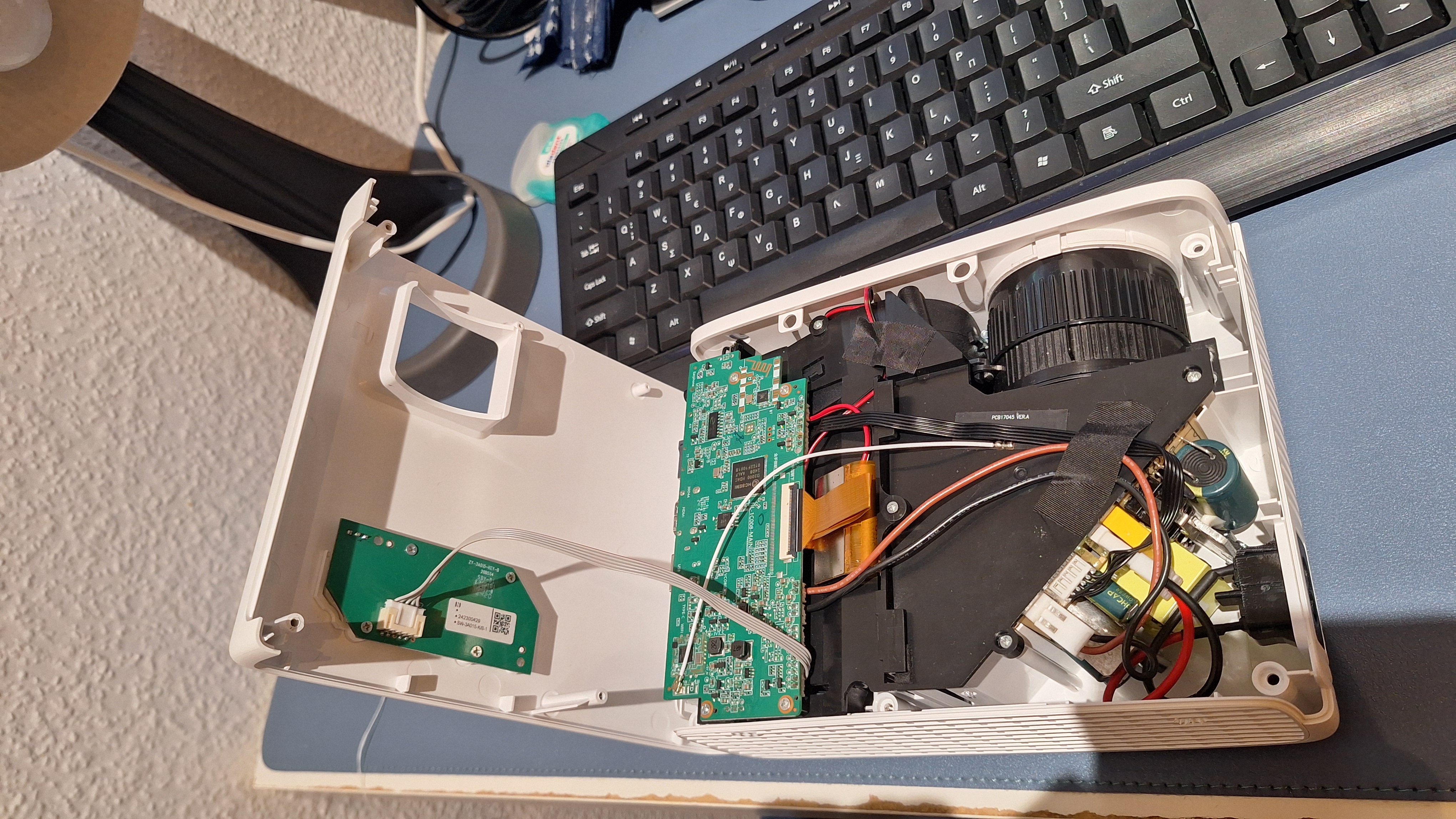
First of all I was smart to not just yank the top shell, since there was a wire connecting the MC to the daughter board with the buttons. Carefully unplugging and unscrewing the board, we see:
Button board
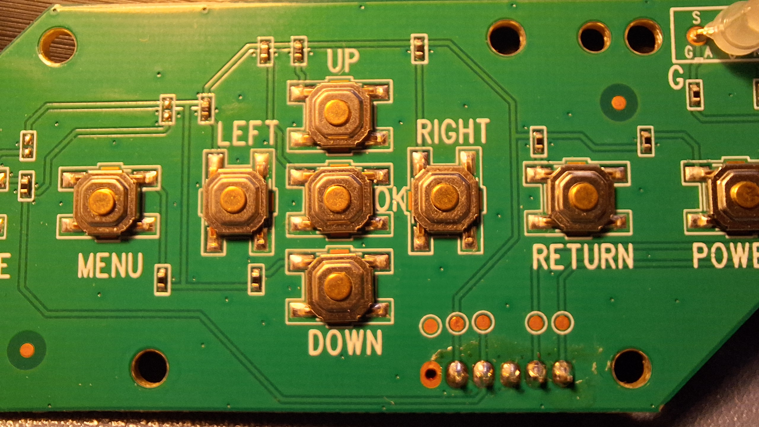
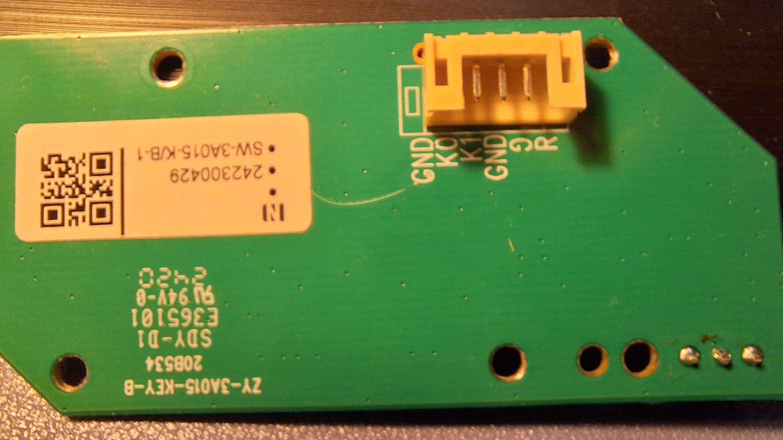
As you can see, there are not enough wires (5) to match the buttons (9) for my assumption. Instead, we see pins marked K0, K1, GND, R, G. Now the R and G are probably the 2 colored LED, which you can confirm by tracing the traces too. Clearly K0 and K1 must carry the data of the buttons. Is it like the membrane buttons which are indexed by the X and Y to ID them? But even those need 8 pins for 16 buttons. Looking at the traces more carefully we see that K0 is connected to 8 of the buttons, with small resistors on the traces. Clearly, pressing the button will complete the circuit, engaging exactly one of these resistors (trace it and you’ll see). Presumably then the MC sensor reads the resistance between K0 and ground to figure out which button is pressed. How does it do that? It sets some Vcc and has a large internal resistor R0 before pin K0. When the circuit completes, the voltage at K0 gets pulled down by the button, but not to 0, rather to a voltage given by:
\[V_i = V_{cc} \frac{R_i}{R_0 + R_i} \approx V_{cc} \frac{R_i}{R_0}\]
These values could be found by just turning on the projector and reading the voltages while pressing buttons. Vcc was around 1.85V, so I could safely continue with using the ESP.
All we need to do is emulate the same action.
The obvious way is to place a transistor in switch mode in parallel to each button, thus providing a secondary path for the current to flow, allowing either switch (original or transistor) to work as expected. But this will need finicky soldering to each button, and there would be no space for the button caps to sit. The alternative is to set the voltage by an analog write from the ESP to K0.
PWM
But the ESP32 C6 variant does not have an onboard DAC (I am reasonably sure about this, but I did see some sources claiming that it does have one), and can only PWM. I hoped that the PWM was by itself fast enough for the microcontroller’s inherent capacitance, but clearly that was not enough. I then tried to make an RC filter, but this failed too since I only had a 25uF electrolytic cap or a 100pF ceramic cap, and nothing in between. The 25uF was way too large and had a very long response time, and instead of instantly setting the voltage to 0, it would slowly go down to it, triggering all the other buttons in between. This was obviously not going to work. The 100pF cap was too small and I don’t think it actually did anything. I don’t have an oscilloscope, but I made a make-shift one with an arduino reading A0 and writing to a serial plotter. Obviously this did not have the time resolution necessary for the task, so it wasn’t clear why it didn’t work in spite of picking large R values 🤷♂️.
DAC
Searching online a little, the MCP4725 was a chip that supported I2C communications and did DAC. I ordered one off aliexpress and waited for a week. It came, I tested it. Since I had not soldered the pins yet, there were loose connections that initially made me think the chip didn’t work, but it actually worked very well. 200ms is a good delay for it to register as a single click.
And so there we had it! I could now control the projector with my phone by sending the esp commands. Except…
Audio
Turns out there are no volume buttons on the projector. I don’t know why. Anyway, the music is output via an aux cable to some old Logitech speakers which have a potentiometer controlling the audio. Presumably I can emulate the volume level by setting the voltage on the output of the potentiometer? So I opened it up to see what voltage the potentiometer was being run on. And I got 0V. Strange. What was stranger was as I was testing for continuity, I touched some pin by mistage and the speakers gave a sound. There should be no reason for a volume control to give a sound right? Thats when I thought a bit more and realised the aux cable was directly coming into the control. Asking AI what this could mean, I realised that the audio signal itself was manipulated by the resistor. By acting as a divider, the amplitude of the audio signal was damped, which obviously could not be controlled by setting voltage. So turns out I have to actually emulate a variable resistance, not a variable voltage. This can be done in one of the following ways:
- A DigiPot chip (MCP4131): This is the resistor brother of a MCP4725. In fact one could build a poor DAC from a DigiPot, but not the other way around.
- A transistor in its active phase: This is super finicky, and the transistor has to be very carefully tuned to prevent it from going out of the linear response region, and is hard to control.
- A Resistive optoisolator: Also called a Vactrol, this uses an Light dependant resistor (Light sensor) controlled by an LED. By setting the LED brightness, one can set the LDR resistance, thus allowing for signal damping. This I could beild with components I have, but is finicky.
The final issue with audio control is that I cannot easily run both controls in parallel. They would both perform a dampings, causing 2 controls rather than one. The only way is to desolder the pot, and connect it to the ESP, which would have to do some logic to keep both controls in sync. Maybe I could replace it with a rotary encoder, and thus only have a “volume up/down” control rather than setting a specific volume. Of course, running a motor to physically rotate the pot is always an option 🙃.
Considering that I will anyway set the volume from the source device, I felt I would not gain much from this. But then again, I don’t see what I’m gaining from using my phone rather than the remote either 😅.
That’s it for today.