Modelling the effect of height on a simple inverted-V antenna
I've been experimenting with inverted-V antennas for portable operation, primarily on the 20-metre (~14MHz) band. One of the factors that I've obsessed about is the heights of the antenna centre and ends, and the effect these factors have on long-distance (DX) coverage. It's often stated that the centre needs to be at least a half-wavelength high (10m, in this case), but I'm interested in the effect that height really has, particularly on radiation pattern.
This is important because an antenna that has its centre only 5m above ground is easy to transport and assemble and, perhaps more importantly, easy to tune. 10m is really beyond the limit of practical assembly and adjustment for a portable antenna, at least in the locations I can operate from.
The inverted-V dipole antenna
As traditionally formulated, an inverted-V antenna is formed from two conductors about a quarter-wavelength long, connected to a central junction, and either pegged out or fastened to nearby supports.
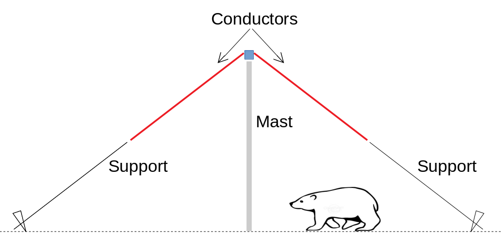
The inverted-V behaves in many ways like a simple dipole, but has the advantage that only a single mast is needed. Because the conductors are not horizontal, the whole assembly is more compact. Of course "compact" is a relative term with HF shortwave antennas -- the ground footprint might still be 100ft for an effective 20m antenna.
The model
I've been modeling the bandwidth and radiation pattern using NEC. This is a pretty arcane piece of software that has changed little since the days of punched cards. For example, the following antenna specification is for an inverted-V with a centre height of 5m and ends at 1.8m, with a conductor length of 5.08m and diameter of 2mm, over an infinite ground with a resistivity of 100 ohm.m (the resistivity turns out to be crucial -- see below). If you already know NEC, then this file probably makes sense to you. If you don't -- sorry, this isn't the place for an explanation.
CM Inverted-V with 5m centre and 1.8m ends, for 20m
CE GW 1 1 0.00000E+00 -1.00000E-01 5.00000E+00 0.00000E+00 1.00000E-01 5.00000E+00 1.00000E-02
GW 2 15 0.00000E+00 1.00000E-01 5.00000E+00 0.00000E+00 4.15000E+00 1.80000E+00 5.00000E-03
GW 3 15 0.00000E+00 -1.00000E-01 5.00000E+00 0.00000E+00 -4.15000E+00 1.80000E+00 5.00000E-03
GE 0 0 0.00000E+00 0.00000E+00 0.00000E+00 0.00000E+00 0.00000E+00 0.00000E+00 0.00000E+00
EX 0 1 1 0 1.00000E+00 0.00000E+00 0.00000E+00 0.00000E+00 0.00000E+00 0.00000E+00
FR 0 21 0 0 1.30000E+01 1.00000E-01 1.50000E+01 0.00000E+00 0.00000E+00 0.00000E+00
GN 2 0 0 0 1.20000E+01 1.00000E-02 0.00000E+00 0.00000E+00 0.00000E+00 0.00000E+00
RP 0 9 36 1000 0.00000E+00 0.00000E+00 1.00000E+01 1.00000E+01 0.00000E+00 0.00000E+00
EN 0 0 0 0 0.00000E+00 0.00000E+00 0.00000E+00 0.00000E+00 0.00000E+00 0.00000E+00
The height problem with the inverted-V turns out to be fundamentally the same as for a simple dipole -- the radiation pattern is highly dependent on the ground resistivity and the height of the conductors. In what follows, I will refer to the antenna layout in the form "Am/Bm", where Am is the height in metres of the mast, and Bm the height of the ends above ground. So the "5m/3m" antenna is one that has a 5m mast, and ends 3m above ground.
I'm working on the 20m band so the wire length will be roughly the same for all the antenna configurations described below. To make comparison easier, I've adjusted the wire length so that the resonant frequency of the antenna is exactly 14MHz for all the configurations.
The soil in my region is non-saline silt, a material which is usually taken to have a resistivity between 2 and 200 ohm.m -- presumably the highest figure corresponds to very dry conditions, where there are few conductive electrolytes in solution. In the following diagrams, I have used a middle figure of 100 ohm.m, but I've experimented extensively with other values.
Radiation pattern
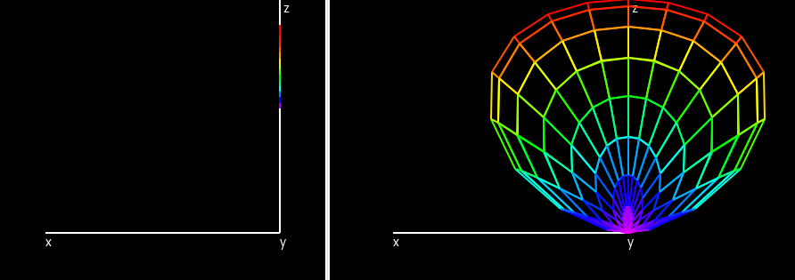
Figure 2 shows the radiation pattern of a 10m/7m antenna, looking along the
conductors. The radiation pattern originates from the ground, which acts as a
reflector, even though the lowest actual conducting part is 7m above the
ground.
The pattern shows two distinct lobes, perpendicular to the conductors. Maximum radiation is at an angle of about 40 degrees to the ground.
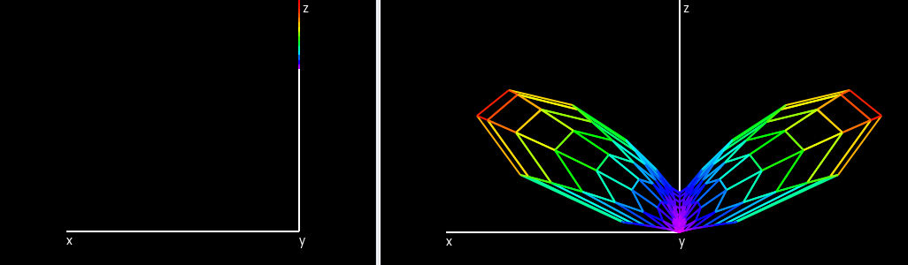
For comparison, figure 3 shows the pattern for a 5m/3m antenna. The angle between the conductors is somewhat larger than for the 10m/7m -- about 133 degrees, compared to about 109 degrees. So its layout is closer to that of a simple dipole.
The problem should be immediately apparent -- this configuration shows no lobes. Instead, the main focus of radiation is directly upwards. There is still some radiation at 40 degrees to the ground, but much less than with the 10m/7m antenna.
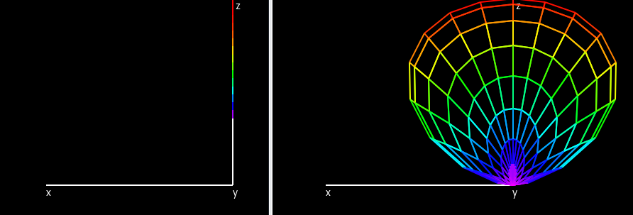
The radiation pattern is not significantly worse with the 5m/1.8m antenna -- as figure 4 shows.
In short, if the mast is only a quarter-wavelength high (5m in this case) it really doesn't matter all that much how high the ends are -- the antenna will simply be warming the air directly above it. Nor does it matter all that much how close to horizontal the conductors are.
It turns out that, with a soil resistivity of 100 ohm-m, to get significant radiation that is not directly upward, the lowest mast required is 6.5m, with the ends 3m high. However -- and this is the big problem -- we can't really predict soil resistivity that well. On a very wet day the resistivity could be much lower, with a correspondingly increased vertical radiation. On the other hand, if the soil is primarily sand, and completely dry, a 5m antenna might be quite adequate.
Matching and bandwidth
It's often said that the bandwidth of a dipole-like antenna becomes smaller, and it is correspondingly difficult to match to the transmission frequency, the closer to the ground it is. However, simulation results for the inverted-V do not really bear this out -- see figure 5.
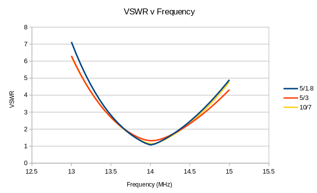
I've adjusted each of the antennas to be resonant at 14 MHz, so the fact that they all show lowest VSWR at the same point should not be a surprise. However, the lowest height offers a theoretically-perfect 1:1 VSWR, whilst the higher antennas do not. In general, the lower the antenna centre, the closer the feed-point impedance is to 50 ohms resistive, and so the better a match it is to a 50 ohm transceiver and feed. Even so, the VSWR is no worse than 1.5 even for the highest antenna centre, so there are unlikely to be any substantial matching losses associated with using the highest antenna that is practicable.
The 2:1 VSWR bandwidth is essentially the same for all configurations.
So what does it all mean?
For long-distance operation, a low-ish angle of radiation is usually advised. With a soil resistance in the region of 100 ohm.m -- typical for my area -- there really is an advantage, in terms of radiation pattern -- to raising the antenna centre to a half-wavelength. Certainly, for the 20m band, the centre needs to be 6.5 m or higher.
The higher the centre, broadly speaking, the higher the feedpoint resistance at resonance; but this resistance is unlikely to exceed about 70 ohms, which should not cause matching problems or losses. The bandwidth does not seem to be affected much by height.
With a soil resistance at its minimum expected value of 2 ohm.m, it really makes little difference how high the antenna centre is. There is a low radiation angle even when the centre is only 5m high.
The height of the antenna ends make little difference to the radiation pattern -- until they get so low that the angle between them is somewhat less than a right angle. Then, it can be difficult to get a VSWR better than 3:1, even at resonance.
Consequently, there's little point raising the antenna centre if you can't raise the ends as well. Unfortunately, if the ends are higher than you can reach, you'll only be able to trim them for resonance by lowering the whole assembly, or getting up a ladder.
Closing remarks
An inverted-V antenna offers increased convenience over a simple dipole, but it shows the same problem with high radiation angles when its centre is too low. Having the ends too low doesn't cause a problem, unless they are so low that the angle between then is somewhat less than a right angle.
How significant the problem is depends critically on the soil resistivity. In fact, if the soil is rocky or very dry, there may be no problem at all.
For portable operation, the best compromise might be to mount the centre on a 10m fishing pole, extended to 6-7 metres. The VSWR with a 50-ohm coax feed will probably be about 1.5:1, so long as the ends are pegged out widely separated.
Published 2019-02-20, updated 2026-02-23
Categories
radioConverted from my Gemini capsule.
Please note: This content is moving to a new Gemini capsule, and there's a new HTML mirror here. I won't be updating these pages in future.